Rendering 3D Graphics: Mathematical Preliminaries
2013-09-01 tech programming graphics math
In this series of articles, we’ll walk through a basic, didactic software rendering scheme for three-dimensional graphics. We assume familiarity with high school geometry and vectors. In this first part, we will explore the mathematical preliminaries. Afterwards, we will implement the renderer using javascript canvas.
Why do distant objects appear small?
This is a fundamental question that we must consider. An object very far away from us appears small, and it increases in size as it approaches us. Why is that, and can we specify how its observed size behaves as a function of its distance from us?
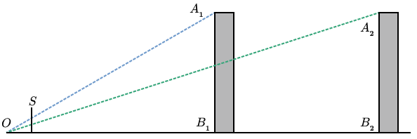
Imagine yourself in a one-dimensional city with two buildings, of equal height, at different distances from you (Fig. 1).

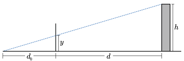
If we look at the angles made by the top of a building, the observer, and the bottom of the building, we see that the angle is smaller when the building is further away. This observation is important, but there is still an element missing. We have no notion of “observed height” in the field of vision. We get this if we put a screen somewhere in between the observer and the object being observed (Fig. 2).
Now we can pose the question more clearly: where does a line (i.e. a ray of light) between the observer and the observed object intersect the screen? One simple way of answering the question is to use similar triangles. Let be the height of the building, the distance between the observer and the screen, the distance between the screen and the base of the building, and the observed height of the building on the screen (Fig. 3).
Then we have
and therefore
This result shows that the observed height is proportional to the actual height, and it varies inversely with . That distance is not the distance between observer and object (blue dashed line in Fig. 3), but rather the object’s distance “inward”, along the observer’s line of sight (the horizontal axis). Likewise, is the distance of the object away from the line of sight, i.e. perpendicular to the horizontal axis. Put another way,
The parameter , which is totally free, has an impact on the way sizes are perceived. We will explore the meaning of later.
Generalizing
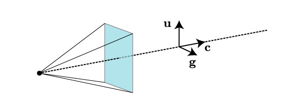
Now that we understand a bit about perspective, let’s leave flatland and consider the problem in three dimensions. I will refer to the observer-screen combination as the “camera”. The camera has several important parameters, such as its location, the direction it’s pointing, the direction that the observer considers “up”, the internal distance , its width and height, etc. In what follows, we will denote the position of the observer by , the orientation vector of the camera by (this is a unit normal to the screen, pointing away from the observer), and the unit vector in the “up” direction by .
You should convince yourself that the position and orientation of the camera are not sufficient to uniquely specify a viewing situation; the up vector is also needed. However, given those two, we can uniquely define a “right” unit vector, via the right-hand rule. The “camera”, just described, is depicted in Fig. 4.
Suppose we are looking at a tree and we want to determine where the leaf at should appear on the screen. We draw Fig. 5.
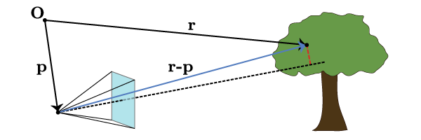
With a bit of thought, we see that this maps directly onto the problem that we solved in one dimension. We must determine the distance along the camera axis between the observer and the leaf (this was ) as well as the distance of the leaf off the camera axis (this was ). The distance off the axis is unambiguously defined as the minimal distance between the leaf and the camera axis; this is equivalent to the dashed red line segment in Fig. 5 meeting the camera axis in a perpendicular. Thus the distance along the camera axis is however much of goes along , i.e. the projection
The vector pointing from the camera axis to the leaf (the dashed red line segment) is then whatever’s left over, so
which is as computationally unwieldy as it looks. Fortunately, we don’t care as much about that length as we do about how it breaks down into components on the screen.
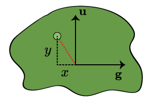
In Fig. 6, we consider a plane parallel to the screen which contains the leaf (the green dot). We want to compute its Cartesian coordinates in this plane (taking the origin to be , right and up being the positive directions). From those quantities, it will be a simple matter to scale them down to screen coordinates. But these coordinates are just projections. The coordinate is the component of the red vector in the direction:
where we make use of the fact that . Likewise, because , we have
Finally we can write down the screen coordinates of the leaf. Again, we take the center of the screen to be the origin of our coordinates, and we take the positive directions to be up and to the right. By Eqns. (\ref{screen-scaling}), (\ref{leaf-y}) and (\ref{leaf-x}), we have
and
Summing up
We now have a straightforward way of implementing three-dimensional rendering. We imagine our scene taking place in . There’s a camera with some parameters, most importantly
Then an object at will appear on the screen at the coordinates
taking the center of the screen to be the origin, with positive to the right and positive up.
In the next part of this series, we will implement this renderer using HTML5 canvas.